Card, mobile credential, payment and security
 By Jerry Banks and Les G. Thompson, co-authors of RFID Applied
The design of the antennas used by RFID tags and RFID readers is one of the most critical pieces in RFID infrastructure. This is because the antennas facilitate the communication between an RFID reader and a tag through free space. Both the reader and the tag utilize an antenna to transmit and receive data. In the case of passive RFID systems, the antennas have the added burden of being able to efficiently collect and radiate energy, respectively. Without well designed antennas there can be no efficient communication between the tags and readers, and, in the case of passive tags, there may not be enough energy to power the tag.
Most antennas are made of a highly conductive material such as copper so it is sensitive to electrical and/or magnetic currents found in radio waves. When an antenna is receiving, the conductive material comes in contact with radio waves and converts the radio wave's electrical and/or magnetic currents into signals and energy that can be consumed by some type of circuit. The opposite is true for a transmitting antenna.
In most cases, antennas possess a property called reciprocity. This means that if an antenna can transmit well at a certain frequency, it can receive equally well at the same frequency.
Most antennas are tuned to operate within a certain bandwidth. This means that the properties of the antenna, such as construction materials, length, and structure, are all precisely chosen to work efficiently in a specified, usually very narrow, range of frequencies. The frequency at which the antenna works best is known as its resonant frequency. When an antenna works well at multiple frequencies, the antenna is said to have harmonic resonance. In most cases, antennas that are designed to work at multiple frequencies are not as efficient as antennas that are designed to work in a very specific frequency spectrum.
As discussed, the construction material of an antenna enables the antenna to convert electric and/or magnetic currents into usable forms of energy. The two components of electromagnetic radiation are the electric component, E field, and the magnetic component, H field. Based on an antenna's design, it will make use of one of these components.
RFID tags that operate within one wavelength's distance from the reader's antenna make use of the magnetic component. If an antenna is designed to operate at 13.56 MHz, its antenna should be designed to operate in the "near field" and utilize the magnetic component. This is because the wavelength of a 13.56 MHz wave is approximately 22 meters. This is not to say that the tag will function at a distance of 22 meters. It won't. The tag's antenna would not be able to derive enough energy from the electromagnetic field at that range. It is important to recognize that the wavelength of the target frequency directly influences how the tag's antenna is constructed.
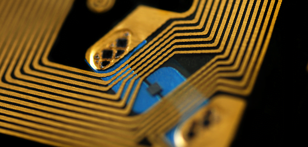
Any RFID tag that is designed to operate at 13.56 MHz will function best in the near field and will most likely have an antenna that is shaped like a coil (see Figure 1). A coil antenna configuration works best for making use of the magnetic component of electromagnetic radiation.
Figure 1 - Texas Instruments 13.56 MHz Tag-ItTM Inlay
It is important to note that the wavelength of a radio wave is inversely proportional to its frequency; thus, a radio wave with a frequency of 13.56 MHz will have a wavelength (approximately 22 meters) that is much longer than that of a radio wave with a frequency of 915 MHz (approximately 32.8 centimeters). The wavelength of any radio wave at a certain frequency can be calculated by the equation λ = c/f, where λ is the wavelength and c is the speed of light in meters per second.
Figure 2 - Radio Wave
Far field antennas operate most efficiently outside of one wavelength's distance of its target frequency. Far field antennas are usually manufactured as straight lines, as opposed to the coils because far field antennas utilize the electric component of the electromagnetic radiation. The most common type of far field antenna is the half wavelength dipole antenna (see Figure 3). The half wavelength dipole consists of two antennas, with each antenna being a quarter of the target frequency's wavelength. Most RFID tags place the tag's processor between both antennas. Based on the previous example, a half wavelength dipole antenna that is designed for the 915 MHz spectrum would require each dipole to have a length of 8.2 centimeters which is one quarter of the 32.8 centimeter wavelength. This antenna would be 16.4 centimeters in total length.

Figure 3 - Symbol Technologies Single Dipole Inlay
An antenna's gain is a key characteristic for RF engineers. Gain refers to the radiation pattern of an antenna. Low gain antennas radiate their energy equally in all directions, while a high gain antenna is direction biased.
High gain antennas have a strong direction and a weak direction. Gain is a very important factor in RFID systems because it allows system designers to "shape" RFID coverage areas. Antennas can be arranged in a portal style configuration (as described in Part 3 of this series) where they are directionally biased toward the inside of the portal. Passive systems benefit from this type configuration because the reader's antennas can concentrate most of their energy on the location where the tag is most likely to be; thus providing more energy to power a tag as it passes through the portal.
Active tag systems benefit from gain as well. In a real-time location system (RTLS), a directional antenna allows system designers to tweak their coverage areas and strictly define the boundaries of the "zone" to be covered by an antenna and reader. For example, if an RTLS zone is defined by the RF layout designer to only cover a single room, the engineers can use the antenna's gain characteristic as one of the tools to make sure that the antenna does not read tags beyond the borders of the room.
There are two basic rules for designing a passive tag antenna. First, the longer the antenna, the more energy it can collect. There is a point of diminishing returns with regards to the length of the antenna, but, for the most part, longer is better. With respect to coil type antennas, increasing the number of rings of the coil is equivalent to increasing the length of the antenna. The second antenna characteristic that is beneficial to collecting energy is the surface area of the antenna. The Alien "M" tag is a great example of a passive tag with a large surface area as shown in Figure 4.

Figure 4 - Alien Technology Corporation "M" Passive Tag
As the width and height of the antenna increases so does its energy collecting efficiency. As discussed earlier, the layout of the antenna depends on how the tag is intended to be used and at which frequency it will operate. Tags that operate at lower frequencies and work in the near field have antennas that are coils. The higher frequency tags that work in the far field have straight edge antennas.
RFID tags are very rarely placed on stationary items (there is usually no point in tracking something that does not move unless you want to make sure it does not move!). RFID tags tend to move regularly and may be placed in many different orientations as the object they are attached to is shipped, carted, or carried. The laws of physics dictate that an antenna will achieve its best reception when its element is oriented orthogonally to the radio wave. This means that the antenna works best when it intercepts the wave at a 90 degree angle; therefore, orientation is crucial if a tag is to achieve its maximum range and transmission data rate capabilities.
Passive RFID tag antennas sometimes look strange because they may be offset at abrupt angles. These angles allow the tag to present some part of its antenna to the radio wave at an angle most conducive to coupling. The half-dipole antenna mentioned earlier is extremely efficient when its orientation is correct, but can be completely useless when it is not. Dipole antennas should only be used in applications where the antenna's orientation can be ensured, so this is why many RFID antennas are "squiggle" type as shown in Figure 5.

Figure 5 - ALN-9440 Gen2 Squiggle from Alien Technology
Most of this discussion has focused on passive RFID technology, but it is important not to forget about the active RFID world as it has its own set of antenna challenges. Active tag antennas do not have the added burden of collecting energy from radio waves to power the tag, because the active tag's battery provides all the power required. This additional power gives active tags some flexibility on how the antenna is constructed. The laws of physics have not changed, but the ability to blast a signal at a relatively high wattage when compared to passive tags can nullify many of the primary design considerations associated with passive tag antennas.
Our next article will discuss the characteristics of radio frequency (RF) and why certain frequencies and antennas are chosen for certain applications.
This article is the fourth in an ongoing series that explains the principles of RFID. It was created for RFIDNews by Jerry Banks, Tecnológico de Monterrey, Monterrey, Mexico and Les G. Thompson, Lost Recovery Network, Inc., Atlanta, Georgia. The authors are two of four co-authors of RFID Applied, John Wiley, 2007, ISBN-10 0471793655; ISBN-13 978-041793656.